By Simon Buddle, Future Ready Homes.
‘Trunk slammers’ is the term used by custom installers in the USA to denote a person or company who provides a simple, cheap in-and-out service with little to no design, programming or any other paperwork for that matter. They usually compete on price and swiftness of service. They are cheap as they have few overheads, and offer nothing to the job above a drill and a few rawl plugs. They are the very antithesis of a custom installer. It is almost certain that the only piece of paperwork they will produce is an invoice.
One of the key reasons they can offer this simple, efficient and cheap service is that they do not need to interact with anyone other than the client. They are not reliant on additional trades onsite and are completely self-contained. TV, TV bracket, drill, cables, trunk slammed, done.

Interdependence
Counter this vision with the world of the KNX custom installer. We are reliant upon trades, potentially communicating only with the client via representatives, and maybe required to provide technical solutions for technology we are not supplying. For example, when you look at lighting, it is often the case that we are the middleperson between lighting designer, electrician, and customer. Designers are rarely interested in the back-of-house equipment; they simply want to achieve an aesthetic that creates a beautiful ambience for the customer. Herein lies a problem for us to solve; how does one successfully deliver a solution that creates the desired aesthetic?
The Circuit Schedule
For me, the answer lies in documentation. Moreover documentation, that if it is good, we ought to be able to charge for and earn money from. It is a skill that sets us apart from the trunk slammers. Inevitably, we will be supplying the lighting control actuators. Importantly, we will be the ones walking around the house editing the lighting designer’s scenes to meet their vision. We all know that the potential for disaster here is massive. Success or failure, we will be held responsible.
First and foremost, it is important that we raise a flag at the design stage to the need for a lighting control design. After all, who will read the RCPs (Reflected Ceiling Plans) and create the circuit numbering list? Who is going to work out the number of DALI drivers and instruct the electrical contractors on how to wire the DALI circuits?
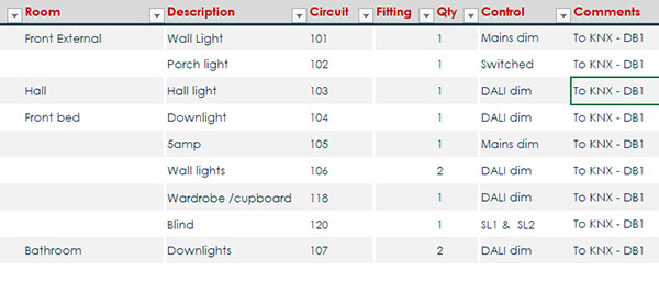
Information gathering is key to creating this first document, i.e. the ‘Circuit Schedule’. The lighting designer will most likely provide specification sheets for light fittings by type and reference them to a numbering scheme on their drawings. This does not necessarily, however, inform the electrical contractor how to wire it.
We also need to know the quantity of fittings per circuit to correctly size our dimming and switching actuators. Many jobs today involve a mixture of phase dimming, DALI, 0-10V and/or DMX controls. Each one of these dimming methods has its own wiring requirements. And so our circuit schedule begins to take shape, with circuit number, circuit name, cable type, cable to and from locations, quantity of fittings and circuit load. Once we have produced this document, people onsite can begin to install lights and cables to them.

Panel building
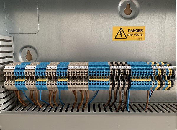
It is at this point that we can retreat to our workshops and begin the process of building the control panels. The panel build, in my view, should not require the electrician to wire into actuators, but should simply have a connection block at the top of the panel.

The Control Panel Connection Schedule
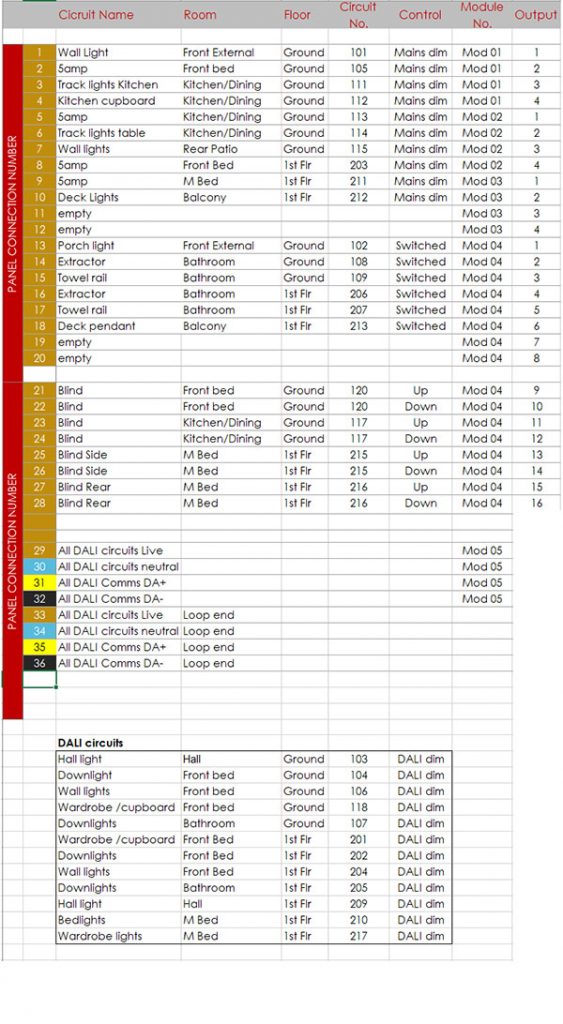
Next, we will need to create a document that tells the contractor exactly which circuit cable goes to which control panel connector. Any errors here will almost certainly be ours to fix in the program later down the line. This ‘Control Panel Connection Schedule’ could be integrated into the circuit schedule, but my feeling is that this sheet is best done in the logical order that the connectors are laid out in the panel. A drawing or picture of the connections noting the number and which circuit cable, is all that is needed.
A note on DALI circuits
It is important that the contractor understands the different approach to DALI cabling. One 5-core 1.5mm DALI cable can serve up to 64 lighting drivers, many more than a typical lighting circuit. I always recommend bringing the DALI cable end back to the control panel. This provides you with an easy method to test end-to-end continuity. It must not, however, be connected at both ends. This would create a loop which will give rise to problems in the DALI communications. It may be worthwhile creating a separate connection sheet that details all of the DALI fixtures, numbers them and defines the circuit layout (for the programmers).

Handover from electrical contractor to programmer
Handover from electrical contractor to programmer will inevitably mean that all faults, mis-wires and the like, will now become your problem and yours alone. One way to make this handover successful is to do a manual on/off from the front of each module to prove the wiring has been done correctly.
Keypad button engraving
The last document to consider is one detailing the keypad button engraving. This could be in the style of a booklet or, better still, a floor plan with flyouts showing each keypad at its location. This should be discussed and agreed with the client. Many view this as an impossible task until after the system has been commissioned, but I disagree. We know, for example, that a dining room keypad is likely to have buttons marked ‘On’, ‘Dining’, ‘Off’ and perhaps one other scene. TV rooms most likely will have ‘On’, ‘Movie’, ‘Relax’ and ‘Off’. It is for us to come up with a library of scene names that we present to the customer. Even though light levels may well be adjusted after the system is fully commissioned, most scene names will remain the same.
Conclusion
These documents serve to provide a structure to the installation of lighting controls. They do not exist until we create them; they are made up of multiple documents, technical knowledge, and our guidance for the client. This work has a value, even if only to us. It eradicates many of the problems that we come across, and in so doing, saves us money. But better than that, if we can show there is value in this work then we can rightly charge design time to create the documents. KNX systems by their very nature cross many disciplines – it’s what sets us worlds apart from the trunk slammer.
Simon Buddle CEng MIET, is a consultant for Future Ready Homes, a specialist in BMS and ELV services system design.


