
In part 4 of this series on KNX IoT, Bruno Johnson and Wouter van der Beek explain the architecture of KNX IoT devices and show how KNX IoT is compatible with KNX Classic systems.
Digital transformation has been one the main strategy topics on company board meeting agendas for the last few years. The opportunity to develop digital services from cloud-based applications requires Internet protocol (IPv6) based network connections to edge devices that become the customer interface. Businesses of all shapes and sizes in commercial building automation have been asking for wireless IoT solutions to make this happen, and KNX Association responded by releasing KNX IoT Point API (KNX IoT).
The high level flow
To ensure backwards compatibility with KNX Classic systems (e.g. KNX Twisted Pair (KNX TP)), the KNX IoT specification has two fundamental mechanisms implemented which are semantic-equivalent to KNX TP: these mechanisms are the configuring of devices and the run time behaviour. Furthermore, the configuration flow in a Management Client (MAC, e.g., ETS) follows the same steps already used by installers. The result is that for installers, there is no difference between using KNX TP and KNX IoT devices. The flow in how to use the new KNX IoT devices is depicted in Figure 1.
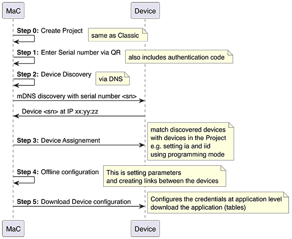
Configuring KNX IoT devices uses all the same information as for KNX TP secure devices, namely:
• Mapping of the serial number to an individual address.
• Downloading the group address configuration.
• Using a password, similar to the Factory Default Setup Key (FDSK) to set up security.
Next to this, a new feature is implemented, namely an installation identification (iid). This allows multiple installations to run over the same IT network. When the device is in run time (i.e. state is ‘loaded’), it exchanges s-mode messages using the configured information. This is depicted in Figure 2.
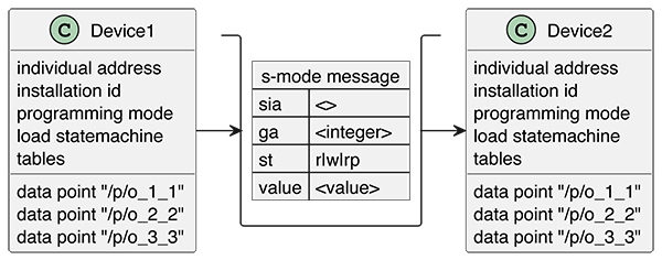
Note that run time communication can be established between N sending devices to M receiving devices, as with KNX TP.
Device architecture
Web addresses, e.g. URLs, are implemented on the device. Each URL that the device exposes, provides information similar to an HTTP server, and each URL has a different purpose. The URLs are defined in the specification and the specification defines what the URL does in the system. Figure 3 shows the most common URLs in a device.
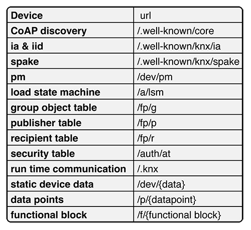
The URLs have different purposes in the system. However, the same information as with a KNX TP device, is stored via URLs.
Figure 3 shows the URLs at device level, and these convey the data such as:
• Serial number of the device.
• Programming mode, (on or off).
• Installation identifier.
• Load state machine status (‘unloaded’, ‘loading’, ‘loaded’), and action to change the state (‘unload’, ‘starLoading’, ‘loadcompleted’).
• Fingerprint of the loaded state, to track if something has changed.
The URL for configuration
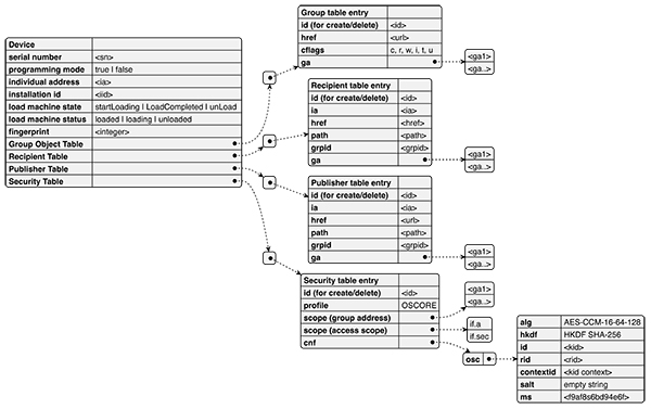
Tables are used to configure the run time communication, e.g., conveying the mapping between Group Address, communication flags, data point (URL), security keys, and the IPv6 multicast address for the group communication.
The following Tables are used:
• Group Object Table – this contains the mapping of the data point URL to the group address, including the communication flags.
• Recipient Table – this contains the group address to group id mapping; the group id is used as part of the multicast address of the s-mode communication or to list the individual address as destination.
(Outwards communication)
• Publisher Table – this contains the group address to group id mapping. The group id is used as part of the multicast address of the s-mode communication.
(Inwards communication)
• Security Table – this contains the OSCORE security keys containing OSCORE information (‘osc’) and the mapping to KNX for group communication, e.g., list of Group Addresses or the unicast access scopes identified by the list of interfaces.
Managing tables
New entries are made with an internet application protocol for constrained devices known as Constrained Application Protocol (CoAP). An example would be a CoAP POST on the table URL using CoAP POST ‘/fp/g’ for the Group Object Table. The values have to define a correct entry. The used ‘id’ will be part of the URL of the new entry. For example, using id = ‘item_1’ will result in a new entry with a sub URL e.g. ‘/fp/g/item_1’. Hence the MAC is in control of defining the entry URLs.
The created URL is listed with a CoAP GET on ‘/fp/g’ as a link format entry in the response. The entry can be inspected by issuing a CoAP GET on ‘/fp/g/item_1’. The response gives the values as per the specification. An entry can be removed by issuing a CoAP Delete on ‘/fp/g/item_1’. This has the effect of the entry being removed from the device, so on a subsequent CoAP GET on ‘/fp/g’ it will no longer be listed. Note that managing the tables for group communication is only possible in the ‘loading’ state.
The URL for run time communication
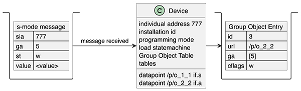
The ‘/.knx’ URL is used for communication of s-mode messages. The s-mode messages contain the following information:
• Group address (‘ga’).
• Sender individual address (‘sia’).
• Service type (‘st’).
The example s-mode flow shown in Figure 5 below consists of a minimum of 2 devices, namely one that creates an s-mode message, and another that receives the s-mode message. The sending device has a Group Object Entry with group address 5 and a URL that represents/contains the value <value> and has the transmission (‘t’) flag. When something triggers the s-mode message to be set, the s-mode message is constructed and sent on the wire encrypted. The receiving device has a Group Object Entry also with group address = 5, and the communication flag write (‘w’) which means that the corresponding URL will be updated with the received <value>.
Multicast s-mode communication
The recipient and publisher table also have entries. These entries govern which multicast address is being used. For example, an entry with ga = 5 and grpid = 1 will result in the grpid=1 value being part of the sending or receiving multicast address. Hence the entries in the recipient and publisher table for the same group address must match, otherwise the sender might use a different multicast address than the receiver.
Unicast s-mode communication – new for KNX IoT
The unicast communication differs by having a different entry on the sending side. The sender has a destination individual address (‘ia’). The individual address must be resolved to an actual IPv6 address. This can be done via common IT protocols such as CoAP discovery or multicast DNS (mDNS). Then the actual IPv6 address can be used for run time communication.
Semantic information: functional blocks and data points (New for KNX IoT)
KNX TP and ETS work on data lengths. Hence the semantic information of what is contained in the s-mode messages is not transferred. However, with KNX IoT, this has been added at the Device level, e.g., data points used to retrieve or set the value have a (datapoint) URL. The (data point) URL can be used to obtain the ‘dpt’ value by issuing a CoAP GET with the query parameter ‘?m=*’. Next to this, the resource /f list of all functional blocks, e.g. CoAP GET on /f gives a list of all implemented functional blocks in link format. The URL of each functional block entry will give the implemented data points on the functional block.
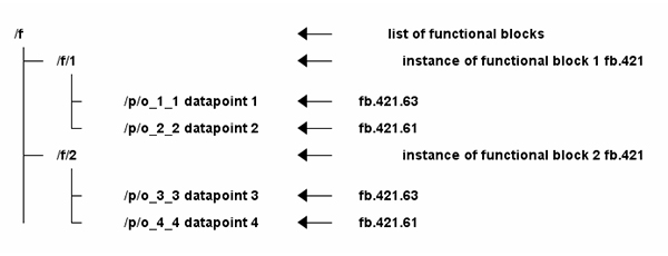
As can be seen in Figure 6 above, this information gives the semantic information in the same form as with KNX TP.
Summary
The advantage of KNX IoT is that it is perfectly interoperable with existing KNX infrastructure, whilst being IP-based. As such, multiple installations can run simultaneously over the same (IT) network using wired (Ethernet/PoE) and wireless (Thread/WiFi/cellular) infrastructure. It has been developed with guaranteed interoperability with existing KNX technology, and it uses the latest underlying internet-based technologies in its specification, thereby making KNX IoT secure by design.
Bruno Johnson and Wouter van der Beek are the CEO and COO respectively of Cascoda Limited. Cascoda is a communications company that manufactures secure IoT semiconductor radios and modules, and leads the development of secure IoT communications standards for smart building and smart city. Its products solve range, reliability, security, power and scalability issues for industrial and commercial IoT through patented innovations and the latest most secure standards, all integrated into inexpensive ultra-low power IoT modules.